DM Inspired
Daniel Murray's protfolio

RESEARCH
An automaton is an early source of entertainment made for kings and queens in the 17th century, they were made populator in the 19th century by the advancement in clockwork mechanisms. The 19th century was the golden age for automatons it produced pieces that cost today around £6.25 million. An automaton is mechanical scene that mimics life, using intricate gears, cams and pulleys, however on the surface they pieces of art that try to be as close to real life as possible. Many automatons are early forms of animation and have stories hidden between their clockwork windings. Automatons are many hand crafted from either wood or metal.


3D printing could be the next advancement to progress the automaton industry. A 3D printer can add a high level of detail without adding significant manufacturing costs, this can be for both the mechanisms and to achieve a realistic scene. 3D printing lends itself more to one of a kind pieces and made to order, this is already how automaton are manufactured. This is why this project will produce a one off automaton art piece.

NUMERIC BASED SPECIFICATION
-
A maxim of 5 pieces in the final assembly
-
Must have at least 2 moving joints
-
Must have at least 10 moving parts
-
To have less than 10% of material wasted on support structure
OPINION BASED SPECIFICATION
-
To be as realistic as possible
-
To have justification for amount of material
-
To maximise aesthetics where possible
-
To entertain on the same level as other automaton
MANUFACTURING CONSIDERATIONS
Before designing considerations have to be made towards the printer type and the material. While designing its import to understand the method of manufacture so that its actually possible to manufacture in the intended method. Factures that decide the manufacturing method are:
-
Minimum feature size
-
Likelihood of successful print in place assembly
-
Surface finish without post process
-
Time taken on post and pre processing
-
Can print in a suitable material


Powder bed fusion was the choice for the manufacturing method as it came out on top in the weighed matrix. This meant that I didn't knew to consider support structures when designing the automaton. The automaton was limited to 200mm x 250mm x 300mm as that's the bed size on the available EOS p110 powder bed fusion machine. Other design considerations were:
-
Minimum wall thickness - 0.7mm
-
Minimum detail thickness - 0.5mm
-
Minimum hole size - 1.5mm
-
Minimum feature - 0.5mm
-
Minimum pin diameter - 1mm
-
Clearance tolerance - 0.5mm
-
Escape holes - 3.5mm
DESIGN
The idea I had for the automaton was my first day at university where I had a sketching class. In the class I had to continually draw circles freehand. This was simple enough so that the automaton only had two motion points, the elbow and waist, but it is still complex enough to prove automatons can be printed in one print.
The human realistic parts were modelled first, this was to get the right proportions to make it look as realistic as possible. The complete human was modelled in Maya (It was modelled fully so that I can use the same model in a future animation), it was modelled using reference images to maximum realism. I then used Meshmixer to manipulate the model to place it into the right position (This is because it was quicker than rigging the Maya model as I couldn't find reference images in the right position). Before exporting to Inventor I added pockets using a Boolean union to save material.


A 4 bar linkage was designed next, this governed the motion needed to draw the circles. Different ideas were prototyped inside of Algodoo. These ideas created oscillation from a rotating wheel. The idea that was chosen works by mirroring the output movement with a fixed ratio. The length AB relates to the waist of the automaton, BC relates to the automatons elbow to pen length. The angles in this system is what's important to produce a circle. linkage 3 can be parallel with linkage 2 which is on the BC length, by making sure linkage 1 and 4 are the same, this is done so that both the angle of the waist and elbow can be taken from single shaft coming up from point A. The angle was taken from point A to the elbow through a gear chain

FUSION GENERATIVE DESIGN
Once the mechanism and body parts where modelled I decided to make the stand from a generative design, this was to save material as using the EOS p110 was expensive. The areas needed to hold the mechanism were modelled as seen in green, the red areas are the areas which the mechanism may occupy and material for the design can be.
Generative design was set up to minimize mass but retain a factor of safety of 2. it was told limiting factors that were decided on at the beginning of the project, the manufacturing method, a minimum thickness of 0.5mm and nylon 12 as the material.
Whilst consulting with a mechanical engineer, the forces where decided on for the stand of the automaton. The study was ran to find convergence results. Generative design reduced the mass to 66 grams which had a factor of safety of 2.06. A cost of £175 was also estimated.
Aesthetics are a import factor for an automaton, therefore I decided to roll back the converged results to make the part more aesthetic. The T splines section of fusion allowed me to edit the stand so that it better flowed into the body to further improve the overall aesthetics. Drain holes were added to allow the loose powder to escape. After these changes a finite element analysis (FEA) was ran to make sure no structural failures had been added.


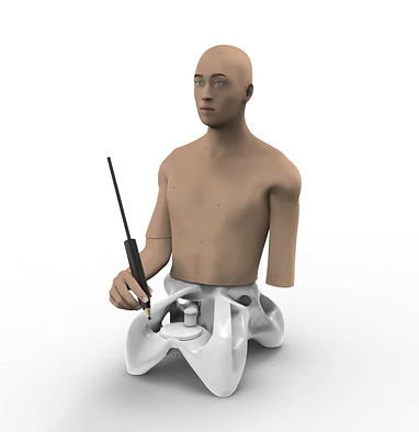
AUTOMATON
I'm happy with how this project ended, it meet all the specification as I think the rendered look real, and they are only painted when compared to the printed version. Unfortunately once the automaton was printed it was difficult to release and some parts of the mechanism are still fused, this could be fixed by adjusting the clearance tolerance from 0.5mm to 0.7mm. The EOS p110 was expensive to run and therefore tolerance testing hadn't been completed on this project.
 |  |  |
|---|---|---|
 |  |  |
 |  |  |
 |